
Pico’s universal 6-way breakout leads are designed to work with any vehicle – eliminating the need to own many specific breakout leads for engine diagnostics.
Pico’s universal 6-way breakout leads are designed to work with any vehicle – eliminating the need to own many specific breakout leads for engine diagnostics.
Designed to save you time and money
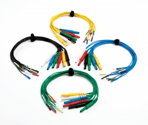
Pico’s universal 6-way breakout leads eliminate the need to own many specific breakout leads for engine diagnostics. The breakout leads are available with 4 different sizes of connectors allowing you to connect to virtually any sensor in the engine compartment — of any vehicle — using just 4 leads. Never again will you need to search your workshop for that expensive vehicle/sensor specific lead.
- Length: 370 to 420 mm (approx. 14.5 to 16.5 inches)
- Connector size:
- micro: 0.6 mm
- small: 1.5 mm
- medium: 2.3 mm
- large: 2.8 mm
How does it work?
Easy to use
The breakout lead is simply connected into the existing cable loom and enables voltage readings to be taken from the numerous sensors in the engine compartment.
The output signal can then be taken from the 4 mm banana plugs into the input of the automotive oscilloscope using one of our premium test leads.

Connecting Pico Universal Breakout Leads
Please read these instructions before using the breakout lead. Pico Technology takes no responsibility for any damage caused through incorrect use. These leads are designed to be used by experienced/professional automotive vehicle technicians who understand the implications of incorrect use.
The signal pins must be identified by wiring diagrams or other means.
It may be possible to cause a short circuit to the oscilloscope unit if incorrect connections are made! A short circuit could seriously damage the unit and will require it to be repaired at your own cost.
- Ensure the ignition is switched off before removing any multiplugs
- On removal of a multiplug keep the plug straight — do not twist the plug out of alignment with its mating partner
- Always connect both the male and female terminals
- The component-only terminals may be connected if carrying out a resistance test. Ensure the ignition is switched off during the test
- Ensure each colour-matched pair of wires in the test lead is used to connect matching terminals in the male and female plugs
- Never partially connect the test leads
- Always ensure that the terminals are correctly located
- Keep test leads aways from hot components, such as the exhaust system
- Keep test leads away from moving parts, such as the alternator drive belt
- Keep test leads away from electrical cooling fans